
Improved shading models in Unreal Engine 4.25 and beyond
Epic Games Rendering Team
July 6, 2020The release of Unreal Engine 4.25 brought a handful of marked improvements to our material system with the addition of a proper anisotropy input, a new physically based translucency shading model, and updates to our clear coat model.

Individuals working in automotive, manufacturing, and architectural industries have long strived to achieve accuracy in their projects. These shader improvements provide a step forward in reducing the complexity of setting up these types of materials without having to use overly complex material logic or hacks to achieve a desired look.
Used in conjunction with our recently updated free Automotive Materials Pack, adding physically accurate materials to your scenes and projects has never been easier. Continue reading below to learn more about these improvements and how they can affect the look and feel of your projects.
Used in conjunction with our recently updated free Automotive Materials Pack, adding physically accurate materials to your scenes and projects has never been easier. Continue reading below to learn more about these improvements and how they can affect the look and feel of your projects.
Improved clear coat
Unreal Engine has supported multi-layered shaders that simulate clear coat materials for some time and improves on the existing model to produce a more physically accurate result. The ability to accurately recreate complex real-world materials is vitally important for some industries and projects. For example, recreating a car paint material is a prime example of a thin translucent surface that often has different normal and roughness properties associated with it, coupled with the underlying surface detail.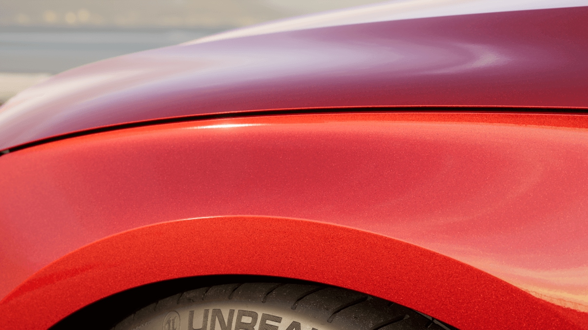

Left, Unreal Engine 4.24 car paint; right, Unreal Engine 4.25 car paint.
The previous clear coat model worked well with environmental lighting, meaning that it worked best when paired with large outdoor environments that took advantage of sky and directional sun lighting. For this release, support for correct directional response to punctual (point, spot, and directional) lights where attenuation and fresnel are most pronounced for lights with directionality.
While the clear coat model is often associated with car paint type materials, it is not limited to them, it can be used to simulate any multi-layered material that has a thin translucent surface over a standard material, and works well with metallic and non-metallic surfaces.
To truly improve the clear coat model, we started by implementing it with our in-editor Path Tracer. This enabled us to generate a ground truth reference using our clear coat model to generate a physically accurate ground truth representation that could be used to improve it across our traditional raster and ray tracing rendering paths.
Setting up and using your own clear coat materials is done by navigating to your Material’s Details panel and changing the Shading Model to Clear Coat. It enables two inputs on the main material node: the Clear Coat and Clear Coat Roughness.
The Normal input is used to control the top layer’s surface texture. To set and control the bottom layer below the clear coat, you’ll want to enable the project setting for Clear Coat Enable Second Normal, which can be found under the Engine/Rendering/Material settings.

With the second normal enabled, use the Clear Coat Bottom Normal output expression in your material graph to set and control the normal map detail under the clear coat surface layer.

The bottom normal more accurately represents complex materials, like the carbon fiber below, or reflective flecks of car paint, which has different geometric or reflective surfaces than the top clear coat layer. Additional examples of this material setup can be found in the Automotive Materials Pack.


Left, clear coat bottom normal enabled; right, clear coat bottom normal disabled.
Added support for anisotropic materials
Representing brushed metals, and other similar types of materials, with proper anisotropic response wasn’t possible prior to the release of UE 4.25 without faking the effect in your materials. With this release, we’ve added beta support for setting up and controlling anisotropy that provides a physically accurate lighting response. This means you’ll be able to control light directionality, in real time, with some simple to use material inputs without the complexity of faking the effect.For example, the rotors on this car wheel have a natural response to light with minimal setup using the new Anisotropy and Tangent material inputs.


Left, standard isotropic response; Right, proper anisotropic response.
Our anisotropic model uses the GGX anisotropic formulation, supporting punctual lights, image-based lighting (IBL) for skylight, and reflections using ray tracing or reflection capture probes with the Clear Coat and Default Lit shading models. This release supports some limited light types, but future releases of the engine will support Directional and Rect Lights. For now, they fall back to an isotropic response with materials using anisotropic properties.
Enabling the project setting flag Use anisotropic BRDF (Beta) opens up the Anisotropy and Tangent inputs on the main material node in the Material Editor.
Enabling the project setting flag Use anisotropic BRDF (Beta) opens up the Anisotropy and Tangent inputs on the main material node in the Material Editor.
The project setting opens up the Anisotropy and Tangent inputs on the main material node in the Material Editor. The Anisotropy input controls the positive or negative roughness of the anisotropic response when the Roughness input’s value is greater than zero.

The Tangent input is useful for specifying the light directionality of the applied texture. The example above uses a brushed metal tangent map to do this. The Anisotropy input controls the roughness of the anisotropic response. In the example below, it moves from a value of a 0 (no anisotropic response) to a value of 1 (a positive anisotropic response). Note that the anisotropic response can use values between -1 and 1.

Anisotropy using a value between 0 and 1, showing an isotropic response to a full positive anisotropic response.
The Tangent input is useful for specifying the light directionality using direct values or a tangent texture map. When only using a normal texture, light directionality is providing an isotropic response. However, when combined with the tangent map, it provides a complete anisotropic response to light directionality.

Left, anisotropic response with normal and tangent maps; Middle, anisotropic response with only the normal map; Right, anisotropic response with only the tangent map.
Improved physically based translucency
Creating certain types of transparent materials that accurately represent real-world behavior for glass, such as tinted color and truly frosted glass has been limited, unless using workarounds or complex setups to make it work. We’ve added a whole new shading model for transparency to do just this, called Thin Translucent, that renders both white specular highlights, and background objects in a single pass with a physically based shader that accounts for light bounces from the air into the glass, and from the glass into the air. And, it does all this while improving the quality and performance of translucent materials over our previous methods.
When creating a material like tinted glass, or any translucent colored material, it needs to add both a white specular highlight and to tint the background when looking through it. In previous versions of Unreal Engine, this type of effect could only be achieved by faking it with separate objects and materials: one to handle the white specular highlights, and another for the background tinting. On top of that, the complexity of this setup also requires blending each one in the correct order.
The Thin Translucent shading model solves these types of issues in a single pass with a physically based shader in your material. It also does this without overly complex workarounds or workflows.

The Thin Translucent shading model solves these types of issues in a single pass with a physically based shader in your material. It also does this without overly complex workarounds or workflows.
Thin translucent materials accurately represent white specular highlights while properly tinting the background in a single pass.
To get started using this new shading model, enable it within your material Details panel by setting the following:

- Blend Mode to Translucent
- Shading Model to Thin Translucent
- Lighting Mode to Surface ForwardShading
In the material graph, add a Thin Translucent Material output expression to drive the material’s transmittance color. The example graph below is a very simple translucent material. The TransmittanceColor drives the color passing through the material. The Opacity input, on the main material node, controls how much light is allowed to pass through the material. Unlike a Default Lit translucent material, when opacity is set to 0, the material is still visible but does not block light from passing through the material.

In the example below, if we look at a Default Lit translucent material compared to our new translucency model, the difference is pretty clear. The traditional model relies on the depth buffer, which doesn’t properly react with the objects directly behind it. Also, shadowed areas are not properly represented, leaving a colored transparent material looking like a clear one.
The new translucency model takes these things into account by providing white specular highlights and properly tinted background representation.
The new translucency model takes these things into account by providing white specular highlights and properly tinted background representation.


Bonus! Free content packs for your projects!
As we continue to push the engine, we also need content that can showcase these updates and new features. Our teams here at Epic have created content that shows off some of these features in exquisite detail, and best of all, you can download them from the Unreal Engine Marketplace for free to use in your own projects!The Automotive Materials Pack is a high-quality automotive-themed pack consisting of more than 150 materials and textures that are ready for your next project. It offers a wide range of material types for car paints, metals, reflectors, leather, and much more. You can read more about the updates to this pack in our blog here.

The Automotive Beach Scene is a perfect showcase for your latest automotive or product design. It consists of highly detailed assets, materials, and textures from the Quixel Megascans library. This scene is designed for cinematic camera moves and a photographic look, and with ray tracing features enabled, it adds another level of realistic lighting. You can read more about this scene in our blog here.
Get Unreal Engine today!
Get the world’s most open and advanced creation tool.
With every feature and full source code access included, Unreal Engine comes fully loaded out of the box.
With every feature and full source code access included, Unreal Engine comes fully loaded out of the box.