
July 25, 2018
An In-Depth Look at Unreal Engine 4.20's Proxy LOD Tool
In this article, we'll explore how the technical artists and engineers at Epic developed this ingenious solution that ensures that the construction and destruction elements found in Fortnite Battle Royale (FNBR) played and looked the same no matter what platform it was being played on.

Consistency is Key
Whether you’re destroying cars to harvest resources in order to build the fort of your dreams, or frantically building walls to avoid oncoming fire, the construction and destruction of objects is a crucial feature when playing FNBR.
When we were implementing crossplay, it was vital for Epic to make sure that every player had a fair chance to win matches, regardless of platform. To do this, the Fortnite team had to come up with a way to reduce the number of draw calls or the number of objects that are displayed on screen at one time to overcome any performance problems that might arise for two of the most important mechanics in FNBR, constructing and destroying objects.
Constructing a Modular World
To better understand the problems that are introduced with player-caused destruction, you first need to know how the buildings in FNBR are constructed. Each building you see in FNBR is built out of a series of modular pieces that can be quickly "snapped" together to make any structure that is needed. This modular approach to building also helps cut down on the number of unique assets that are required, saving precious resources like memory. This is because you can reuse the various modular pieces in different ways with different materials and textures to give your buildings an unlimited amount of variety without having to load additional objects into memory. You can see an example of the types of results that can be achieved when using modular construction in the image below.

The building that is on the left-hand side of the image (above) is constructed using only the nine Static Mesh Actors that you see on the right-hand side of the image, minus the various Trim and Props that live inside each building. Constructing the buildings in this manner also makes it incredibly easy to display the player-caused destruction because all that needs to be done to signify a piece has been destroyed is to disable both the rendering and collision of the destroyed piece. While this method of displaying destruction works well for both PC and consoles, it does present some issues on less powerful platforms, such as mobile devices. The reason for this is due to the sheer rendering cost of drawing the 350 to 400 individual pieces that make up the buildings in FNBR. In the following GIF, you can see just how many pieces make-up a typical building.

While this is not an issue for PC and consoles, it is an issue for platforms like smartphones where the entire scene needs to be composed of less than 1,000 pieces.
Now that we understand a little bit about how buildings are created as a whole, let’s take a look at how each component is built, as that also plays a role in how destruction is displayed. The following flowchart breaks down how the information in the rest of this document is laid out.

Less is More (Optimized)
Even with the modular type construction that is used in FNBR, you will eventually hit a hard limit on how many objects you can have on-screen at one time. This hard limit, referred to as Draw Calls, presents a big problem as each platform you can play FNBR on will have a different amount of draw calls that can be displayed at one time. To ensure that each platform that you can play FNBR on has a smooth and stable framerate, each Static Mesh that is used in FNBR contains multiple Level Of Detail (LOD) Static Meshes. LOD’s are a commonly used video game optimization technique that works by displaying a new lower triangle version of the Static Mesh when the Static Mesh is a certain distance away from the camera.
The above image shows one of the many modular wall Static Meshes that are used to make the various buildings you see in FNBR. When you are very close to the wall, you will see the Static Mesh that is on the far left-hand side of the image above. As the camera is moved further and further away from the wall, the different LOD's will be displayed, like in the following GIF.

When this technique is applied to an entire building, you will get something that looks like the following image.

On the left-hand side of the above image, you can see what the original building looked like and on the right-hand side, you can see what the building looks like using only the last LOD. While the version of the building on the right-hand side is what we want, it is still made of far too many pieces to be rendered efficiently on some platforms. To address this issue and still be able to display player-caused destruction, we are going to need to employ some new tools and some “old school” Static Mesh production techniques.
Kicking it “Old School”
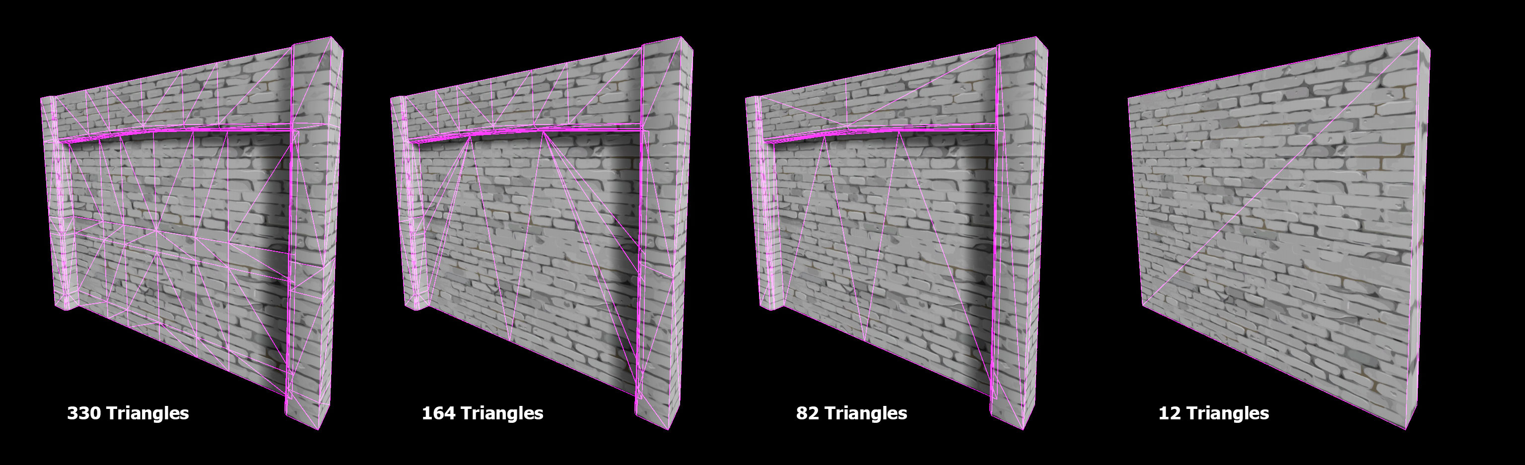
Before we take a further look at how player-caused destruction is displayed, we first need to take a look at the very last LOD that is used in each of the modular Static Meshes as it was created in a special way. Using the UE4 Static Mesh Editor to open up one of these modular building pieces and then forcing it to display the last LOD will give us something that looks like the following image:

While this looks like an average Static Mesh, make sure to take note that the Triangle count is 12 with the Vertex count being 18. While these numbers seem low, they are actually smaller than you can get when using a Digital Content Creation (DCC) to create a cube that is the exact same size and shape. In the following image, the same modular building piece was created in a DCC and then exported to UE4. The created Static Mesh is the exact same size and shape but notice that this Static Mesh has six extra vertices.

While having only six extra vertices does not sound like a lot, it can quickly add up. For example, if the above piece is used 30 times in a single building, it would add around 180 additional vertices to the building. Now take the 180 additional vertices and multiply that by 100 structures and you get 18,000 additional vertices that have to be rendered but are otherwise not used. To get rid of these extra vertices, these modular Static Meshes where adjusted in the following way:
- First, each modular piece that could support it was forced to not use any Smoothing Groups.

- Next, the Static Meshes UV's where set up so that there would be as few UV Islands as possible. For this modular piece, the front and back faces of the box where mapped to the entirety of the 0 to 1 UV space. Then, the parts around the side where all welded together and scaled to match the current setup of the modular pieces.

- Finally, the Normals were modified to make sure that any smoothing artifacts on the vertical faces would be mitigated as much as possible.

When all of that was completed, the newly fixed-up modular piece was exported and then imported over the existing piece. This same process was then applied to the last LOD on every single Static Mesh in FNBR.
In the next section, we explain why all of this was done to show player-caused destruction.
They did ‘What’ with Geometry?
Now that all of the modular parts making up the building all have LOD's that are in a state that uses as few triangles as possible, the Hierarchical Level of Detail tool (HLOD) was then used to generate a new version of the building, which looks like the following image.

This new version of the building, referred to as Medium HLOD or MHLOD, combines all of the very last LOD's into one single Static Mesh and Texture. This significantly reduces the number of triangles that are needed to display the building, reducing the triangle count from 50,820 to just 2,880. This is a huge improvement, especially for lower-end devices like smartphones. This new version of the building will only be displayed on lower end devices and only when the player is about 30 meters from the building. This also helps to reduce the number of Materials that the building uses, which will further help reduce the number of resources that the buildings require to be rendered.
Going the Distance
Although the following information does not have to do with player-caused destruction, it is still good to know. While playing FNBR, you might have noticed that when viewing a building that is far off in the distance the destruction might not show up. This is because the very last LOD that you see is being generated using the Proxy Geometry tool. The Proxy Geometry tool is a new tool that was developed in-house as a replacement for Simplygon and is used to further reduce the triangle count of the MHLOD version of the building. While this version of the building does not show player-caused destruction, it is important because it helps reduce the rendering cost of the building when it is really far from the camera. When running the Proxy Geometry tool on the MHLOD version of the building used in this example, the building goes from 2,880 triangles to just 412 triangles. Now, the building is not going to look great using only 412 triangles as you can see from the image below.

Keep in mind that the 412 triangle version of the building will only be viewed at very far distances, so it will be very hard for the player to tell that it looks like the above image. To get a better idea of how this all comes together, check out the following GIF. In this GIF, we are seeing the building go from its highest triangle count version to the lowest triangle count version as a player would when playing.

Armed with a little bit more knowledge about how buildings are constructed and the tools that are used, including why those tools were used, we will now go over how this all comes together from an idea to a production-ready tool.
Technical Art to the Rescue
Now that we know a little bit more about how the buildings are constructed, we need to take a look at how to apply destruction to them so that it can be seen when the MHLOD meshes are in view. One of the key factors driving this is the need to show the player-caused destruction without changing anything about the MHLOD building. The reason for this is that changing or replacing pieces to show player-caused destruction would negate the benefits of having the MHLOD version of the buildings. Since this is a somewhat complicated issue to solve, we are going to need to call on a special kind of developer to help us out - we are going to need to bring in a Technical Artist.
For those of you who are not aware what the role of a Technical Artist entails, a Technical Artist (or TA) is an artist, coder, and designer all rolled into one person. From fixing complex Material issues to debugging a Blueprint, TA's can fix many of the problems that arise during development. This is why TA's are often tasked with developing solutions to some of the more complex problems as they generally know more about how all the systems and tools that are needed to create video games are interconnected and work with one another. For this particular task, we need a TA to come in to help break the problem down into its smallest components so that a simple yet robust solution can be created.
Breaking it Down
When trying to figure out a solution for a problem like this, the first thing that you want to do is break the problem down into its basic parts. This way you can get a better idea of all the parts that are involved and make small yet successful bits of progress. With this taken into consideration, the TA's broke the problem of showing destruction on the MHLOD buildings into the following components:
- First, we need to add a new property called HLODDestructionIndex to the BuildingWall class that all the buildings use.
- Then, when building an HLOD, each Actor the building uses will be assigned an index which is not dependent on order.
- Next, each building foundation will need a Render Target big enough for 1 Texel per destroyable piece.
- Once that is completed, we would then need to modify how Mesh Merging is used with HLOD to add the ability to copy the Max LOD and apply custom vertex colors to the newly generated Static Mesh.
- Note that the Vertex Colors should be quantized such that using R, G and B gives 65k in values which should be more than we need.
- Now, whenever a piece of a building like a wall or a floor is destroyed, we read the HLODDestructionIndex value and then write the color black to the texel that is assigned to it. This will destroy the building piece as normal and the HLOD mesh sees no state changes but looks destroyed and the only work we did was to issue a Draw event containing 1 pixel per destruction event.
- Finally, in the Material, we take the ID that is packed into the Vertex Color and use that to look up into the destruction texture and then collapse the vertex to the origin (for example, scaling to zero) if the texel read is zero (a destroyed section).
Now that the TA's have a plan of action, they can start to build a prototype inside of UE4 that will allow them to see if this idea will work or if they need to go back to the provable drawing board.
Luckily for the TA's, the above approach worked like a charm, resulting in the MHLOD Static Mesh being destroyed without adding any additional rendering overhead like in the following GIF.

Now that the TA’s prototype works, it can be handed to a tools programmer to turn it into a real production tool.
Building it Back Up
Now that the prototype has been built, tested and reworked so many times that it is hard to distinguish the prototype from the original idea it will then be handed off to a tools programmer to be re-built using C++. The reason that we want to rebuild this in C++ is to ensure that things will run as fast as possible and also be as optimized as possible. Rebuilding this tool in C++ will also enable the needed properties to be grouped in the existing UI in a location that makes sense. Once that has all been completed, we can try this out in-game, like in the following video:
Tools You Can Use
In conclusion, we hope that this article helped you gain better insight into how the Technical Artists and engineers here at Epic addressed the problems that destruction caused with the introduction of Crossplay. Without their ingenious solution, the symphony of destruction that players can unleash in FNBR would not be possible.
Best of all, the tools mentioned in this blog post can be found within the 4.20 release of UE4 and we’re extremely excited to see how the Unreal Engine developer community puts them to use.
To read more about these tools, check out the links below:
Proxy Geometry Tool - The Proxy Geometry tool set was developed as a way to increase your Unreal Engine 4 projects performance while keeping the visual quality of your project uneffected.
Hierarchical Level of Detail - The Hierarchical Level of Detail tool or HLOD helps reduce the number of Actors that need to be rendered for the scene, increasing performance by lowering the number of draw calls per frame.